Monday, September 30, 2013
Quarq or Accuity
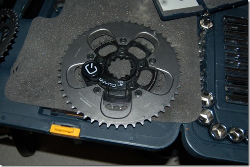
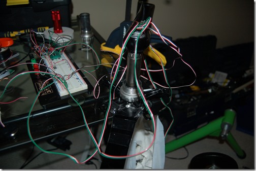
Quarq or Accuity? Guess which is which.
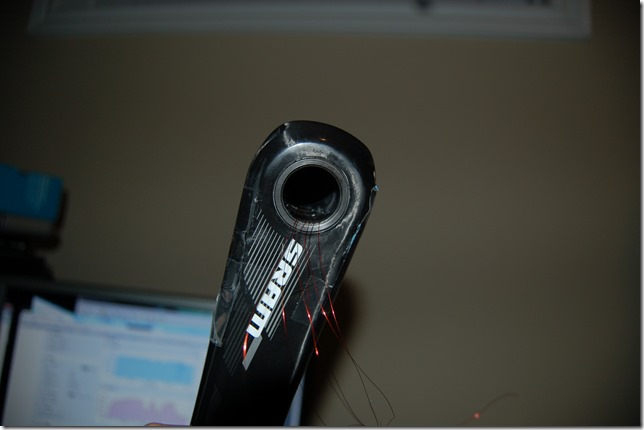
Testing right side then left side!
Close, almost perfect. Going back to check calibration data. This one requires some "Decoupling" math which I'll get into when I do a serious post soon. Very very busy week.
Friday, September 27, 2013
Quar-ccuity (or Accuiq?) and ANTride
Quarq + Accuity
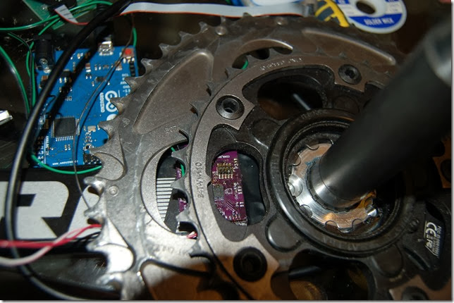
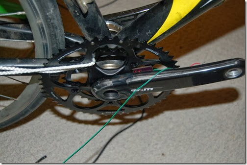
The Quarq + Accuity crankset is almost ready. Major changes since the Rival based version include:
- Zero offset (or “calibration response”) programming has had a major change. Rather than a separate function that takes over control temporarily, it uses the existing code in the main body read the strain gauges. This probably sounds unimportant, but it’s the result of a peculiar issue where current drain was increasing when I tried to zero only the right side. By leaving it to alternatively read left then right sensors like it normally does it maintains currrent draw as is.This improves stability and how “clean” the code is. I think this is the result of the higher impedance wiring used combined with a capacitor issue. Either way, this makes the system more robust over the usable voltage of the battery.
- When you use a cycle computer to tell it to Zero offset (or “calibrate”), it reads back the offset (eg –417 when I zero my Quarq Cinqo). Unlike Quarq, which translates this value to 1/32 N-M, mine is left as the raw ADC values. I’d be surprised if Quarq isn’t doing this as well and it just happens to be “about” 1/32 of a N-M. For this Accuity build each value is 1/20.26th of a N-M for the left and 1/17.50 of a N-M for the right.
- This Build uses a different strain gauge setup for the right leg compared to the Rival unit. The S900 crank is using the actual intended setup that was intended for Accuity and not re-working the existing setup of V3. V3 was more sensitive setup, but it’s a pain to wire and difficult to integrate the setup into the board without some lead wire resistance mismatching.
- Detection for when the rider has stopped pedalling gives better / “cleaner” restart values. It’s still not perfect, but it generally doesn’t interfere with data. David Johnstone over at cyclinganalytics.com has been picking apart my L/R data and pointing out an issue that the values go to 100% left value when you resume pedalling. I haven’t fully nailed this down but I’m almost there (I think).
- Reduced power consumption. The Rival crank has a different voltage drop resistor and received the power from the battery directly. Now the strain gauges are powered from the 2.048V linear regulator on the ADS1248. That’s a 1 volt drop plus the same 750 ohm in line resistor. The strain gauges are operating at less than 0.5V. This is important because in the planned sleep mode (ie: not riding) it can turn off the strain gauge power supply.
The next major step (to hopefully happen Sunday) is doing my initial indoor tests. Kurt pointed out to me via twitter that I could use the small cup cone on the lever skewer. I didn’t trust it when I got the trainer so I swapped it. I’ll carefully try it. I’m not 160lbs climber. More Clydesdale.
ANTride
This isn’t really a real name. I’ve had a lot of traffic thanks to Ray over at Dcrainmaker.com due to tweeting in response to the Muin review. He linked to a short post (here) asking for feedback on his week end review.
What is ANTride? The short explanation is that cycle trainers are predictable devices. Things like TrainerRoad and the Lemond trainer have taken advantage of this to create “virtual power”. This is the indoor equivalent of what iBike tries to do outside. Kurt built the inride as an application of their regression curve for average power on their site. However, they were very clever having already tried a basic cycle computer before – they incorporated a spin down test to to measure acceleration and possibly rolling resistance to increase the accuracy. As you can see from the review there are a few people asking about ANT+ since it’s a BTLE only device.
If you’ve used a powermeter then you know that outdoors it can be tough to dial in on a number and hold it since there are so many competing factors such as wind, hills, other riders, etc. Eventually you get better at this but it takes a while. On a trainer this is much easier. If you already own a powermeter then there isn’t a point to this device. If you don’t own a powermeter, or one is out of financial reach than this can be an attractive option to a lot of people. Off season training means training with power.
Why build this if you can indoor train at a computer using a speed sensor. A few reasons.
- You want to capture that data to your ANT+ cycle computer
- You don’t train in front of a computer (Garage, basement, spare room, etc)
- Improved accuracy
That last one is something that Inride does well at a fraction of the price of a direct force power meter. However it comes at a price. Location. In order to determine the acceleration of a wheel accurately a simple magnetic switch sensor doesn’t cut it. This means that none of the Speed interpolators can have that level of accuracy. That is why Inride senses at the roller. It’s higher speed means it can detect accelerations much more accurately.
So going forward there is a choice here. I can achieve the same accuracy as Kurt Kinetic Inride putting it within 2% of a real powermeter but only if I can get more accurate measurements of acceleration. This is where people might say that “all hope is lost”. Hold tight.
There is another way to pull this off with very good accuracy. Enter the MEMs gyro. I discounted this for the powermeter (though I’m thinking about it again, mainly in terms of wanting to offer every possible feature out there at a fraction of the price – and a high speed mode will need it). A gyro attached to the wheel can provide very accurate information.
I’m going to test the magnet sensor on my kurt kinetic and see if I can make the calibration work.
I’m low on available development time so I’m going to think about this some more. In the meantime feel free to leave a comment or email me at kwakeham@gmail.com.
Monday, September 23, 2013
DIY Power without the Meter
That really didn’t take very long for a proof of concept!
Okay, so you can see the code in the background there and ANT+ is getting super easy for me especially since I re-use a lot of code. The real goal would be setting this up as a small updatable device so that other trainers can be configured. The best way to do this is to aggregate data from multiple peoples rides on different trainers with powermeters to develop quality regressions that can then be uploaded onto the device for people who don’t have powermeters but still want to train with power.
Sunday, September 22, 2013
ANT+ Trainer Power transmitter?
I was just reading DCrainmaker’s latest post on the a new silent trainer here, the Elite Turbo Muin. A lot of the feedback from people has been asking if the App does power why couldn’t they build in power transmission via a sensor!
Seriously!
Here is how I can do this, and I’ve thought about doing it.
- Get the regression curve
- Make it yourself with a real powermeter (Powertap, Quarq, SRM) with the LINEST feature in Excel for a 3rd or 4th order polynomial.
- Use the CSV file from the App and regress the curve yourself
- Using the reference code from Nordic Semiconductor in the SDK you setup a speed measurement with a reed switch / magnetic sensor and measure rotational speed.
- Two lines of code
- Calculate power based on speed
- Update ANT+ transmission
Saturday, September 21, 2013
Enclosure and Carbon Fibre Cranks
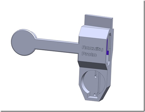
The enclosure is getting closer to what I want. I’ve ditched the wrap-around plastic on the drive side arm and I’m contemplating using a wire from the BB Axle (plastic cap) to the electronics enclosure. This is similar to Pioneer’s design. It’s not great but it’s easier and may help with speeding up the process to beta and compatibility initially with other cranksets.
As for calibration of the carbon fibre crankset, it looks very linear at least initially. Way to go SRAM for QA. This’ll make the comparison of the Quarq unit to Accuity so much easier. It’s expected to be linear as a new crank but my background research shows that at higher usage factors it’ll go non-linear. I can’t get the specific answer out of any manufacturer I tired so far. If it goes non-linear it can be calibrated out, however a much more sophisticated calibration is needed – unlike the simple hanging weight test.
A load cell rated to 1000lbs is tested at multiple points including 1000lbs and quotes linearity. If anyone ever gets a power meter from me they will be getting documentation on the calibration values and it won’t just be a single weight test. I want it tested to at least about 170N-M of torque which correlates to a 100kg person’s entire weight.
The calibration values all come out to be nearly identical. The weights that were used were measured on a calibrated scale at work and confirmed (to the 0.1 gram) with my household scale to the gram. The linear regressions are almost perfect
I plotted the R^2 values. Looks nice and linear to me. Also, keep in mind that the number of counts is only on a 16 bit scale. I’m capturing at 24 bits, but the last few are noisy. At 16 bits it’s noise free (it’s actually noise free to 18 bits, but it’s hard to do 18 bit math with a 32 bit microcontroller without pointless programming).
Back to the carbon crank, until there are some fatigue cycles on the crank, a new carbon fibre crankset is giving reliable and accurate readings. Time will tell once the carbon starts to fatigue.
Tuesday, September 17, 2013
Enclosures and More
It’s been a few days since I’ve written anything. It’s been a very busy few weeks. Nothing overwhelming stands out but the enclosure design in progressing. I’ve also been prepping the Quarq + Accuity comparison unit.
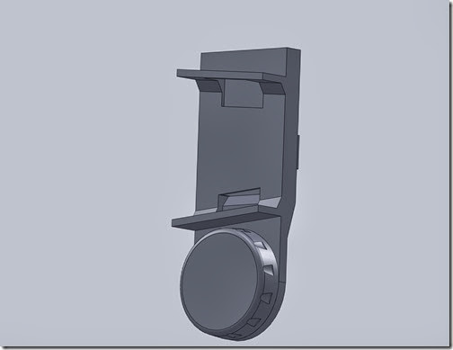
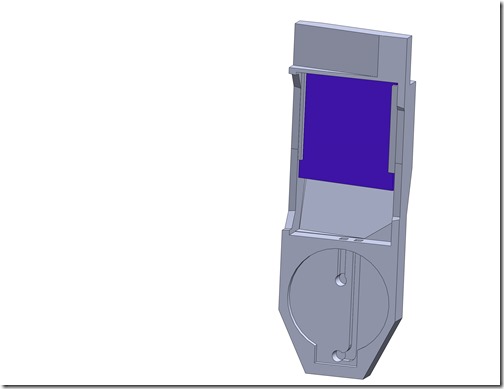
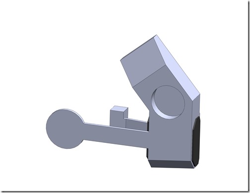
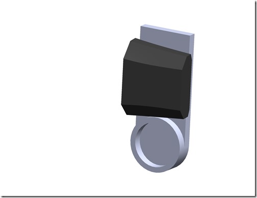
Above is the first design attempt. A small amount of plastic wraps around the outside of the arm and protects the wires leading to the axle.
Generally it’s hollow inside and the enclosure supports an off the shelf battery holder. This contributes to the larger lower enclosure size. I’m concerned about clearances all around. I generally don’t like this design, however the board was specifically designed to go on the backside of the drive arm between the chainrings and the crank arm.
I attempted to diverge a little from the original design and try a setup with the board and battery above the crank arm. This is not idea because all the fragile wires from the strain gauges have a greater distance to travel. This leads to all sorts of issues. The most ideal is to keep things short. This comes back to trying to place the board inside the crank arm.
Having given up on the second design I’m revisiting how to make the first more effective. I’m integrating the battery holder into the design to minimize size and weight. There isn’t much room around the crank arm. Lots more work ahead.
On to the Quarq + Accuity unit.
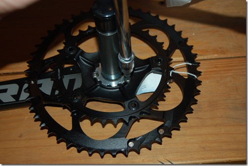
First the S950 (S900 compact version) crank has it’s spider removed. Just 3 simple Torx bolts. I wish everyone would use this design. SRAM (well Quarq really) should push this as the standard for everyone who wants to make a crank with removable spider. Right now the Cannondale, FSA, and SRAM units are not interchangeable. We can use ANT+ but can’t have a physical standard?
Then I removed the Quarq unit from the S975 Cinqo. The Cinqo holds much much tighter tolerances and was on a bit more snuggly. I’ll chalk this up to China / Taiwan manufacturing versus American. While swapping the chain rings requires recalibration, removal of the whole setup does not. There has been some talk about the removal of the chain rings and torqueing the bolts over at the Slowtwitch forums. I haven’t done this myself and don’t plan too. In the event I do then I’d like to check the calibration with the iPhone app – which as soon as I get a Wahoo dongle I can as I was given a “broken” iPhone 3GS. The screen is crack but still functions fine. Amazing. Maybe I’ll just send it in to Quarq with the Accuity prototype in tow and get them to calibrate it then?
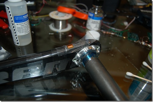
I prepared the crank arms carbon fibre just like Vishay’s tech notes say to and applied the strain gauges.
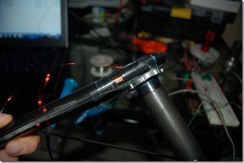
Another picture with a better view.
I also installed the inside torque sensing strain gauge. All gauges were installed very quickly but I haven’t tested them yet except for resistance. Carbon prep time is much faster as abrasives can eat into the epoxy very quickly. DO NOT USE CONDITIONER A. Conditioner A is a mild acid, and a mild acid eats the plastic. The neutralizer (base) is fine to use. When sanding using isopropyl alcohol only.
Recently I’ve been testing the boards and their connection and function with the Texas Instruments ADS1248. Remember the four boards I made up and transmitted fine? I didn’t test the ADC interface. There were some bad connections on this board with the ADS1248 which meant it was acting very stupid. Finally got it working just before bed time last night.
Here is a picture of testing the board with my four sensor setup Rival arm used for thermal and force sensitivity testing.
So that’s everything. I’m hoping in 1 – 2 weeks to have a Quarq to Accuity comparison but don’t hold your breath. I’ll get the bike on the trainer inside to do this and if I can find another Garmin Edge 500 or similar for a decent price I’ll setup them both up outside for a ride.
Sunday, September 1, 2013
Prelude to Launching a Beta Test
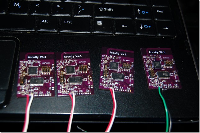
Above you see the culmination of 13 hours of work – 4 simple circuit boards. They aren’t fully tested at this stage either. They have all been programmed and checked to see if they transmit but I still have to test the ADS1248 interface to make sure they measure the strain gauges and the cadence circuits. Bad connections between the nRF51422 and the circuit board could mean that a board can’t function as a power meter.
This marks the beginning of preparations for the beta test.
I would like to diverge a little to talk about startups, and the effort it takes to get to this stage.
I was sent an article on Inc.com (here) about startups, depression, burn out, drive, ambition, etc. It’s a very good article and it reflects my own work to a smaller extent. It can be a serious struggle to balance a day job, build a “company” and a powermeter (I consider these two different things and the first is neglected), and maintain a level of health and activity, all while staying up to date on several industries. Oh, and when I have a chance Tweet and Blog.
My goals have been lofty but I am very proud that I have a functioning powermeter of my own design on my bike right now. Over the three prototypes I’ve built in the last year It has low power consumption and though it has some minor issues it’s working very well and is quite usable – unless it rains. It still needs a little more programming and an enclosure but it’s done 100km outside. This is far from an endurance test but it’s a good start. The last two rides were solid and now I have to track down a bug – one that doesn’t quite interfere with it’s operation. So now I’m moving on to building up my beta test units.
Recently I received an email asking about the beta test. It reminded me that I’m behind my original schedule. I had posted a couple of times that I’m off schedule because I had to revise the circuit board due to Balun problems. It’s a major pain to be on the verge of something and spend even second of your free time to just find out something doesn’t work.
So the email frazzled me a little but I’m seeing that right now is the time to grow thicker skin. I’m finding I need that more every day. I’m starting to see comments, even from the innovative and startup laden Waterloo, Ontario area extolling how they could build a powermeter, but that they’d rather be riding.
I’ll never be a pro cyclist but I can be a a pro engineer. That’s my choice, and I made that choice long before I ever loved cycling. I made that choice when I was five years old - I decided I’ll engineer for the rest of my life. And that means hands on, not just desk work. This is one project that I chose to dedicate myself to. If it doesn’t pan out I’ll know a lot more, and if it does maybe those who would rather ride than engineer can ride a little better, a little farther, a little faster all by using something I made.
As it stands am now 2 weeks into oblivion. Sadly planning is part of the business side and as I mentioned I’ve neglected. However, I’m not three years off thankfully! I think I need another month or two. I might have to start looking south for testers. Boulder Colorado maybe?
So, I’m on the cusp of building up beta units, talking to potential users on a regular basis, getting feedback, documenting everything, etc. If I thought building a powermeter was going to be a daunting task, an even larger task lay ahead of me and one that I am even less familiar with.
I was advised that there are two ways to go with building a startup. Either you protect your concept with a patent, or you have to build a product and customer base. Reviewing the patent situation it’s apparently that you can’t really patent much in terms of powermeters. So that’s left me with only the later option. I’ve been exploring this via the concepts of Lean Startup and Minimum Viable Product. It’s a huge learning curve, but I’m been working on it about 20 hours a week for the last year.
Nothing is perfect. There is a lot to live up to in the cycling market. There are going to be arguments about products. There will be those who ridicule me, telling me that it’s not needed or telling me that I’m a disappointment. Customers who, no matter my intentions, will tell me that my product is junk – even when I offer them a new replacement or a full refund or both. A startup isn’t an easy prospect. It’s not for the faint of heart.
If you’re reading this blog as a potential customer, you’re the most important person to me and I’ll do my best to make things right.
If you’re reading this blog as a hardware hacker, I want to share this knowledge with you – hackers lead directly to innovation. You can’t invent something if you don’t know how to do something. So what if you have to build a diy bulky version of DI2 or an Arduino cycle computer, you’re learning and eventually you’ll have enough background and knowledge to innovate.
If you’re reading this blog as a fellow startup, then research hard, work hard, believe in your product, and know when to pivot or exit. Try hard to maintain a balance in your life. Startup’s are hard and can cause burnout, depression, and more. I’m so glad that testing now coincides with riding but I did a poor job balancing things until this point. Learn from my examples. However long something should take, double it. At least then you’ll have a buffer.

