Monday, August 26, 2013

Accuity V4.1 Working Well; Safety First!

I went on my third ride last night (fit file here) with zero dropouts, but there is one spike for some reason I’ve yet to determine. The Garmin connect link is here for those who are interested. To do is check the calibration. To get to a minimum viable product I need to finish the enclosure and auto shutdown when not pedalling for a few minutes. 150 hours of life (estimated) doesn’t seem that long when it spends 22 hours a day not in use.

I made a video tonight explaining how pedal based power meters such as Garmin Vector and Look Power Pedal work. It also explains how Resonant String Gauges for the Swedish Adrenaline indiegogo project likely work (here). The video is still uploading, and it’s fairly basic whiteboard video. It’ll be here later tonight. Direct link / post tomorrow.

I want to apologize for taking video in an unsafe manner for Accuity V4.1’s first ride. Please don’t do the same. It was stupid and reckless endangering myself unnecessarily. If you must take video buy a cheap camera mount or a GoPro. I ordered a mount today to take some video. It’s cheap from China but I suspect it’ll do the job.

Wednesday, August 21, 2013

Accuity Powermeter Testing Video and Data File

DSC_9616

Testing Accuity V4.1 Bicycle Powermeter

I’ve also made my Garmin Connect file public (Garmin here, Fit File here) so everyone can download it. There are anomalies and this is a first test!
  • Bad battery connection means that it loses it’s zero and causes massive offset showing as huge power numbers (up to 18000 watts!)
  • A few times during the video it’s noticeable that if the crank hasn’t been rotated in a while and during the first rotation there is an abnormally high power number. There is an overflow issue or double tripping of the Magnetic reed switch causing an erroneously high power for the first 1 – 2 rotations then it stops. I didn’t see this as much in the later part of the ride. I think it’s an ultra low cadence problem.
  • The bump issue is related to the magnet position I found out later during the ride. If I hold my legs level with my right leg on the back side it can trip the reed switch multiple times in a very short period with half my weight on it. Obviously a false 200+RPM reading combined with 100NM torque will give over 1000 watt reading. This is solved on SRM and Quarq by putting the magnetic pickup not in line with either crank arm. Smart for them, I missed this in designing.
  • Reads back a random value when told to calibrate. Minor but would be useful to implement an actual value. It’s standard with Quarq and SRM.
  • Have to calibrate twice – once for each side. Not really needed but it’s left as a debug measure. It could be useful to know the offset of each side as the ANT+ protocol only supports one value.
  • Sorry it’s hard to see the actual values in the video.
Some more pictures
DSC_9612DSC_9624

Tuesday, August 20, 2013

SparqEE: Enabling Cell phone tech for DIYers


Originally I started this blog as a more general purpose hacking site, however it’s been a little more dedicated to sports sensors and ANT+ the last few months. I’ve talked about Kickstarter a lot lately and its potential role with my powermeter project, so it goes without saying that when something cool pops up I’d let my followers know about it.

The short: Easy to use Cell phone data technology for Raspberry Pi and Arduino. Some cool additional boards too!

Keep in mind that my V3 power meter was Arduino based, so this could be a cool extension for ANT+ technology. Switch my code into receiving mode and broadcast your data for live triathlon / race telemetry for coaches, friends, and data / tech geeks like me on the web! If interested sign up for the kickstarter here. These guys have the engineering skills and creativity to make this product happen!

So what could you use it for? Followers of the Tour De France will likely know that the HTC Columbia team did something very interesting with their ANT+ enabled phone here. Their ANT+ sensors (speed, cadence, heart rate and power) talked to their ANT+ enabled cell phones and the cell phone relays that data to the HTC website. Up until now recreating this would be a very difficult prospect – few phones are ANT+ enabled (even HTC ones) and you’d have to deal with making a server to receive and display the data. Sparkfun has some cell modules but they’ve always come off difficult to me and not very inviting to use.

SparqEE is doing the heavy lift on this! They are going to have libraries for easy coding with both Arduino and Raspberry Pi as well as having a server for your projects to communicate with! This means easier cell phone enabled projects. Wouldn’t it be cool for a coach to watch your data in a competitive tri, or a hard training ride remotely?

They also have some really cool low cost add on modules to help fill out your projects in addition to the easy to use shields for using the same module on either an Arduino or Raspberry Pi. The add on board that entices me most is a relatively low cost GPS board. Low cost bicycle tracker? Call it up and find a stolen bike so long as it has GPS signal / power / isn’t in the middle of nowhere. How about a remote g-force logger – lots of sporting applications. Track that “24 hours of Lemons” race or your downhill skiing and snowboarding. People involved in SAE competitions like Formula SAE or Mini Baja can now easily add telemetry! Great experience and all for a about a hundred dollars to set it up.

image

Some other suggestions for the SparqEE that comes to mind:

Garmin sells a online tracker for about $200 dollars. You could easily build your own for less and add a lot of feature sets such as relaying other useful data. Track your fellow Nordic Skiers on a trail perhaps? Or your Dog?

image

Competitive Geocaching – track others as they get close to difficult to find / challenging to reach caches! Relay their locations to your cell phone and race them to the goal.

Or maybe do you own Top Gear Style race with a Google maps tracking. This is my favourite. I’m a cycling enthusiast but I also love spirited driving. I’d love to have a distance race between friends!

This project has a lot of potential, and I’ve been avoiding the obvious things: Household monitoring, finding your car in a parking lot, finding your significant other in the parking lot before you find your car, etc. Take a look at it and see if it suits your application here!

Some other items of interest from the team shown below

Press Release: http://www.sparqee.com/kickstarter/20130820_pressRelease.html
Pictures: http://www.sparqee.com/kickstarter/20130820_pics.html
Blog we posted: http://www.blog.sparqee.com/?p=53

Monday, August 19, 2013

Accuity Works - but no video yet

DSC_9605

On August 12, 2012 I made the first post on my blog (here) which was a recap of an old site I was working on over a year earlier. I was interested in a powermeter but as a Masters student it was too expensive so I became curious. I had been using my Kurt Kinetic trainer with a regressed power curve as a training tool. After talking to a coach about my training software and potential development (virtual coach) using regressed power curves I can rightly say I was very discouraged from pursuing anything further. A combination of lack of time, thesis, training for triathlons, looking for a job, and that small advice from the training community led to shelving the project. I should note that my local bike shop in NL (here) was quite supportive. Below is what I’ve called V1 now, or version 1, which never had a dedicated circuit board.

Next came V2 out of my curiosity for strain gauges which continued. It used a similar arrangement for the strain gauges as V1, but now it was a full bridge rather than half bridge. This is important as I now understood more about how sensitive the wheatstone bridges are to temperatures. I demoed this shortly after building at the startup accelerator Communitech to one of the coordinators, but honestly it didn’t go well. The problem is a lack of experience plus it really wasn’t ready for prime time. It was hard to setup, get working, and keep working and transmitting well.

DSC_8869

This lead me to develop V3. V3 had the exact same electronics but it fixed several problems. The biggest being that an antenna in the axle doesn’t transmit well and running wires through it was a terrible idea. So instead of a bending bridge arrangement for the left arm, I used a double shear gauge inside the axle. It worked great, but V3 was huge and prevented me from running in the 53t ring safely without damaging the circuit board and connections. Major shortfalls include power consumption and noise on the ADC.

And so V4 is born. I switched to a different microcontroller, the new nRF51422, which allowed me to drop the power consumption and move to a one chip design (microcontroller and RF transceiver in one chip). Combined with a new, lower noise (but slower) ADC called a Sigma-Delta rather than the Successive Approximation Register (SAR) ADC but it kept the power in check all with more noise free bits. I built a reflow oven, and learned a lot about RF (and I still know very little), but after a second attempt at a circuit board (V4.1) I was successful. I had named this version Accuity which took me ages to come to. I think it conveys the precision of the unit with the double c’s to remind that it measures two legs.

DSC_9606

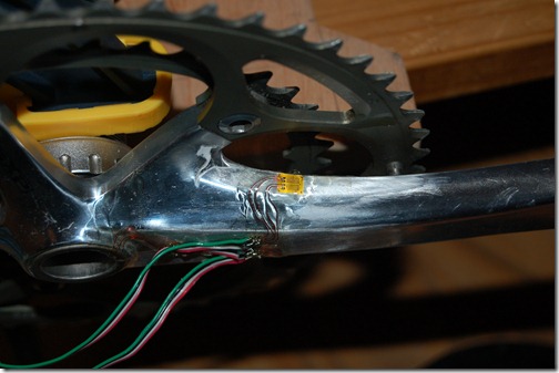
I’ve spent a lot of time getting this working in a table top debug form, and slowly transferring it to a bike crank. I am low on strain gauges so I decided to reuse the instrumented crank from V3. You can see the programmer hanging off it above. The programming cable can’t be removed without removing the chain ring which is another mistake to be rectified further down the road. After hours of debugging and rewriting the de-bounce filter for the magnetic switch, I found out that I had accidently been sending “Power_L” over ANT+ and not “Power_T”. I had previously been debugging something and it required that I simplify things, but I forgot to revert the code. I’m ready to move on to the next phase of testing on my bicycle trainer and……..FULL STOP.

DSC_9602

It’s hard to tell from the above picture, but the cup that holds the skewer cannot clear the area around it. Thus I can’t test it inside! I’m willing to tighten it to the point I can turn 60 – 70 watts by hand, but I don’t dare put my weight on the frame. I just bought this frame recently, and I don’t want to damage it.

This means that I can only “test” it outside, but I can’t compare its data with anything. The plan was to regress a power curve myself on the kinetic and switch out to the prototype and regress another curve and see how they line up. My other option is to rent a powertap again, but this is a 200km round trip to London Ontario. The final option, and possibly cheapest is to get another cassette and a derailleur to setup my old GT Series 4 such that I can ride it as a single speed on the trainer. More money is required to solve all problems.

Tuesday, August 13, 2013

Accuity V4.1–95% Complete!

DSC_9596

It’s coded. It’s been running for about 70+ hours of testing and programming and forgetting to disconnect it on a CR2450 and still has life. It’s been extensively calibrated on the bike (this is necessary for removing bending from the left leg sensor). All parts (crank included) is less than $200 dollars. However skilled labour required is very high in terms of both skill and time. No, I won’t be selling these for $200 – my time is very valuable – but I still think a dent can be made in the $1500 mark. Powertap is forging the way.

To do:

  1. Move the Reed Switch closer to the Quarq Magnet location
    • My Madone has a different magnet taped on. The Nice Quarq ring magnet is on the old GT GTR Series 4.
  2. Put on Chain rings
    • RIGHT! I knew I forgot something.
  3. Test on Trainer
    • But I’m so out of shape.
  4. Test on Road
    • See above…? I’m really out of shape lately.
  5. Finish Enclosure design
    • Don’t ride in the rain until then!
  6. Torque effectiveness and Pedal Smoothness
    • Easy to calculate, but need to spend more time modifying the nRF51422 ANT+ library to support it.

It’s taken a while, but it’s doing well. It has 16 – 18 bits noise free. I’m using only 16 bits of the 24 the ADC is as it’s just about 100% noise free. It’s about 15 and 24 counts per N-M. Essentially this relates to < <1% error BUT keep in mind there is some sensitivity to pedal offset. It’ll likely come in at the competitions 1.5% – 2% quoted marks.

Okay, so maybe not 95%. I am very close. I am off schedule though, but honestly not by much:

imageimage

I really didn’t include a prototype stage! Major oversight. However, if I build another 4 in a few days I’m 100% on schedule. No, I don’t expect this to happen. I need another month. So mid September for beta group I suspect.

What can it do?

It’s a powermeter so:

  • Measure Left and Right legs torque individually
  • Measure Cadence
  • Calculate Power
  • Transmit power data on the most common wireless powermeter standard - ANT+
  • Calculates L/R power balance
  • Costs a lot less than the competitors, but a lot of build time (Mixed feelings!)

Here are some pictures

Calibrating the non-drive side. The 5k on the right is to keep the rope stretched and the cranks level. 15kg “calibration weights” measured on calibrated scales at work which are good for 0.1g.

DSC_9594

Debugging: Programmer talks to Accuity. Arduino receives the serial output. The .NETMF Fez Panda talks to another ADS1248 that’s also measuring one of the sensors to ensure Accuity is reading right. The Gripper is connected to a test strain gauge beam to ensure the Fez Panda ADS1248 is working.

DSC_9595

Accuity up close. Personal. And poorly soldered!.

DSC_9599

Serial Terminal and ANT+ Display Simulator.

DSC_9600

So long for now