Wednesday, April 24, 2013

Timelines

image

I’ve created a relatively aggressive schedule for myself which should have prototypes for beta testers to use around the end of June or early July. If you look closely to the picture above you will see that I’m on track with the coding, the strain gauge design evaluation, and ahead of things on the thermal side. However, the gyro evaluation isn’t started – and it’s due to happen yesterday.

At this point I don’t see it as likely to start. The problem is that the gyro has to be running at all times. Stable startup times are long, on the order of 100ms, so you can never really shut it off. When it’s on, it's 4ma. The gyro alone would kill a CR2032 in under 50 hours without readout enabled. In short, current draw is high too. But these were all issues I mentioned before and said I would work with and maybe find a way around. That is looking less likely to happen to meet the build schedule.

In news, SRM is evaluating a rechargeable power meter for mountain biking. SRM generally uses the idea of primary cell lithium that are not user replaceable. IE: Has to be sent to Germany or Colorado. However seems they are warming to the idea of rechargeable.

This brought a single thought to me. It comes down to if I went with a rechargeable I could have my gyro, but sacrifice operating time (50 – 80 hours depending on battery), or pursue coin cell operation but still potentially be forced into rechargeable due to not being able to source 1000 ohm gauges (especially the double shear gauge for the left torque measurement).

I have ran all the tests on the strain gauge setups for rejection of unwanted forces and I have to make a choice on which arrangement will be used. In order to do this I need to measure total current draw ASAP on the current setup. The choice of battery and gyro are coming by the end of the week or early next. This will lock me into a path. I’m close to a decision, but I’m not there.

Sadly there is little advantage to gyro, thought it might increase the accuracy over a magnet setup. The battery choice is the answer to all of this.

Lots of parts on the way though in the meantime.

Sunday, April 21, 2013

Thermals and Calibration

DSC_9177

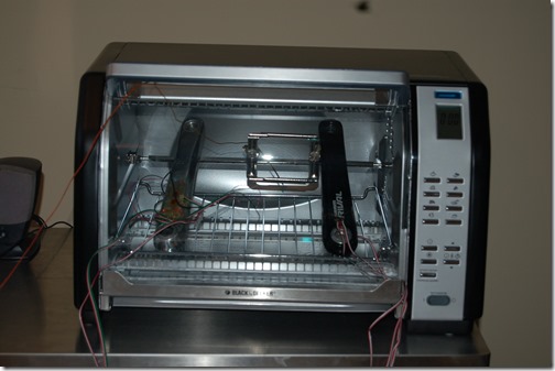
Toaster oven meet test setups. Test setups, toaster oven. Now that introductions are done, let’s get down to preliminary business.

The above picture shows two test crank arms – one from V2, and one built up for this testing.. Each crank arm has two different sensor setups. Four in total and all very different. There is a thermocouple inside the oven. This is the first test measuring four sensor setups. Five tests have been conducted. The first three are really for figuring out how to deal with setting up an actual experiment and the last two are the real data experiment. I used an insulated tape on the thermal couple to measure each crank arm independently during the last two tests. More after the break.

Tuesday, April 16, 2013

Compensating for Something–Thermal

image

No, this has nothing to do with a midlife crisis. It has all to do with heat, expansion, and the dreaded thermal drift in power meters. In one of my last posts, here, I talk a good deal about a minimum viable product but managed to segway myself  into a discussion on thermal compensation.

Thursday, April 11, 2013

Unexpected Prototype - SRAM S900

I committed to something today. I ordered a Sram S950 (S900 compact crank version). This is a huge departure from the SRAM Rival. The S900 has two carbon fibre crank arms and an aluminium spider. This will allow me to answer the carbon fibre fatigue question. That is, does carbon fibre crank arms exhibit a change in the stress-strain slow as they fatigue and will it result in non-linear and hysteresis effects.

It will be getting instrumented as one of the beta units. I am trying to track down a used Quarq Cinqo Saturn or an SRM unit that used the S975 crank. This would allow for the first two crank based power meter comparison! If anyone out there wants to lend me their Cinqo Saturn spider I’d appreciate it. However, I very much doubt anyone is going to loan me a 1500 dollar piece of hardware so that I can take it apart. I’ve seen some old SRM wired units going for 500, but all have been Dura-Ace. So if I find one at a reasonable price I’ll try and pick it up in the coming months. Then that will mean that some lucky person in the beta will get two power meters to trial. Whoever that might be (Ray perhaps?) will be provided with a custom logger for their bike that can log two power meters at the same time. Unless, one is a wired SRM and then I’ll have to work something out.

Here is where I am stuck. To test the carbon fiber fatigue theory which I’ve talked about, I need some very heavy usage. I can do this in two ways. Artificially with an MTS machine, or through a lot of logging of real world usage. One is fast, and one is cheap. Both are good. The old adage of pick 2 holds valid.

Specs:Sram S950: 170mm, Compact 50/34, GXP BB

Wednesday, April 10, 2013

80% Coded for an MVP and Thoughts


For those of you who are unfamiliar with the term MVP in the context of a startup, it is simply the “Minimum Viable Product”. A minimum viable product is a product that is to enter the market and test a market hypothesis. Things in today’s economies change quickly, very quickly, and because of that Eric Ries recommends that business plans are essentially a terrible idea for a startup. For SRM powermeters were a startup, for Cycleops less so, Quarq even less so. And the rest of us, we are behind the curve in some respects. Everyone’s startup now revolves around something novel about the power meter, but nothing equivalent to the revolutionary effect of a powermeter.

Monday, April 8, 2013

Kicad–Another Learning Curve

image

For my initial circuit boards I used Cadsoft Eagle. In my undergrad I tried it and I very much disliked it due to it feeling “dated”, but I was busy doing mechanical engineering. As a result I decided to push my EE-like ambitions out, and moved on with my life.

When I was hit with the need to design PCBs I had found that the hobbyist community had already strongly developed around Eagle. To be honest, I’ve never been sure why. I mean, in the 6 years I haven’t been using Eagle it hasn’t changed – well, 6 years ago it crashed a bit, and now it doesn’t. But the interface looks identical and as a result I’ve had to change my Solidworks / Ansys mind-set towards a very different workflow.

However, today, I hit on a legal dilemma. CADsoft Eagle’s free version is for non-commercial works only. If I create the circuit board for my beta group with Eagle, then I have to reproduce it later in another package if I wanted to sell it. It’s better to bite the bullet and do this up front. I don’t have a specific timeline built up, but I plan to start ordering parts within a week (resistors, capacitors, inductors, battery holders, etc) and designing up the enclosure (which will be produced after I get a new PCB up and running).

Kicad is a free and open source alternative with no commercial restrictions as far as I can see. I’ve been doing a tutorial to get my bearings and it’s not too different from Eagle – except it looks and feels 5 – 8 years newer. The workflow and buttons are similar but like anyone who switches from one 3D software to another: the combinations of CTRL, ALT, Shift + Mouse L/R/Middle + movement are all different. After using one piece of software a lot, say ANSYS Classical, then moving to Solidworks, then to Ansys Workbench, means you are constantly confusing yourself on how to navigate a simple space. It really makes you feel a bit like an idiot – luckily nobody really notices.

To be honest, I wish I had access to Altium Designer as Nordic already has reference schematics and layouts in these. However, Altium Designer is not a cost feasible solution ($7245 US) and I’m sure the learning curve would be even worse. I’m sure an experienced designer would be able to make use of the design software better than I could. However I’m at best a Mechatronics kind of guy.

Friday, April 5, 2013

Code Mostly Ported and Other Things

image

I’ve been working in the background on things that most people will find dull – more coding. No major breakthroughs, but no breakthroughs are needed at this point. I’ve ported about 65% – 70% of the code and what is left to do is below. More after the break.

Monday, April 1, 2013

nRF51 Interrupts–Not what I expected

The interrupts are acting a little different than I expected based on my current limited experience. They seem to be active when the pin is in a certain mode rather then when it changes state. This means that when DRDY (DataReady) asserts low, it wakes up the microcontroller and keeps it awake. The nRF51 can’t go back to sleep until DRDY asserts high. I’m sure I could code around this or some other options exist but luckily I don’t have to – and here is why:

image

When in continuous read mode I need to send it “NOP”, or No OPeration, which is fancy for 0xFFh. Into the first NOP command the DRDY asserts back to high, and once the read operation is complete the nRF51 can go to sleep. DRDY will only assert low when a new conversion is ready.

For those who are interested in the how the ADS1247 operates when reading multiple inputs, instead of NOP you can send a change input command while in continuous read. The next conversion will be the other selected channel.

Here is something neat that you can do with this too. My strain gauge arrangements are full wheatstone bridge differential inputs, meaning that each sensing arrangement requires its own differential pair. However, if you want a half wheatstone bridge for generic strain inputs you can put a voltage divider to input of MUX0, and have 3 inputs to half-bridges. This would be a quick and easy solution for multiple thermally compensated sensing arrangements. I’m currently testing this way with a workpiece I made while in North Carolina at Vishay’s training course. It’s a differential bending beam so it is a half bridge configuration. I’m using two 10k resistors (Vishay 1 ppm, 0.01%) as a voltage divider on MUX0, and this differential beam input to MUX1. I have another full wheatstone bridge wired to MUX2 and MUX3, but sometimes I’ve just sent it to MUX0 and MUX2. That means an ADS1248 with 8 inputs could do 7 half bridge sensing arrangements!

The 2000sps max for this chip is spread over all channels then. So if you set the read rate to 2000sps and have it over 4 input setups then that is only 500sps for each channel. I am planning on testing to determine the ideal rate, but right now this chip is so low noise that I suspect I won’t need to pass 320/channel (640sps total) which will put me in line with most production powermeters. That would give 160 per revolution at 120rpm per leg.