Wednesday, February 27, 2013

Convert your old SRM power meter to ANT+

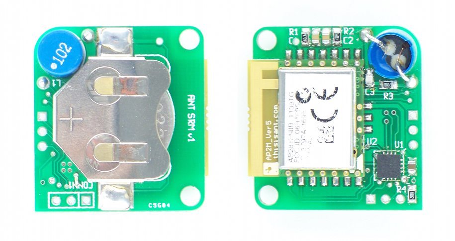
So a while ago I noticed some posts in the ANT+ forum by Mark Rages. Turns out he’s the “electronics guru” of Quarq. He has an old tumblr site here. Where he shows an MSP430 + the ANT+ AP2 module to use as an intermediary and convert old SRM powermeters to ANT+.

This is like my ANT+ to BT2.0 for another purpose… a much more complicated issue too. If you have an old SRM this should be very useful to you!

Image from markrages.tumblr.com

This is impressive! He’s gotten power consumption down to 160 microamps from a coin cell. He’s a much more experienced man than I in regards to this stuff.

There was also a discussion on Facebook’s “Training with power” surrounding ANT+ head units. Mark’s post in the ANT+ forum was removed or I can’t find it, however the opensource.quarq.us site still exists with his python scripts for ANTware II. It’s located here.

A big shout out and thanks are deserved for Mark I think. Cheers and thanks for promoting ANT+.

Monday, February 25, 2013

Kurt Kinetic Power Curve

This data was gathered using a Garmin Edge 500 and my prototype L/R measuring Power Meter which is still being worked on. The latest upgrade to my prototype power meter is here

image
Power versus Mph.
Blue dots are actual test points, the black is the 3rd order polynomial fit, and the red is the Kurt Kinetic regression they provide here.

Now in a semi sensible unit (power and km/hr)
image
When you accelerate the regression curve can’t capture the extra torque, and thus extra power. This is the same problem in coast down. Stored energy in the flywheel is released but you aren’t putting in extra power. I’ll add to this over time, but for now, Kurt Kinetic Road Machine = solid investment!

V3 Upgrade–New Right Leg Sensors

DSC_9082

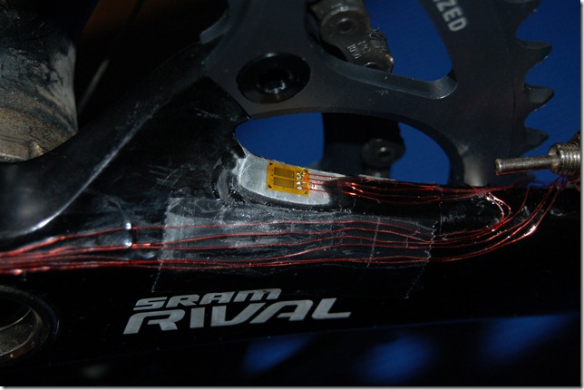
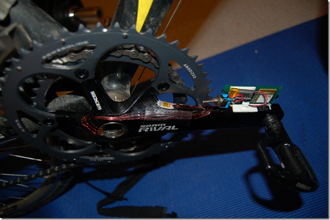
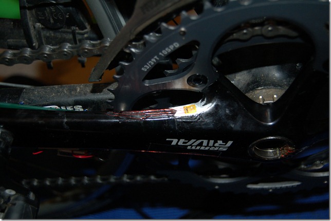
So V2 had some superior measurement features. If you recall here I discussed about how applying a torque through my foot caused the readings to skew. So installing a couple of strain gauges like V2 on the top and the bottom create a very good and more isolated sensor. This is ACTUALLY how Rotor Power works, but the gauges are on the INSIDE. I can’t do that, not unless I drilled holes… this would cause stress risers and likely lead to fatigue failure.

As an idiot, I used two gauges from different batches. This caused a mismatch in the wheatstone bridge causing a huge voltage offset. I therefore needed to drop the gain, but I didn’t have a high quality resistor to use, so I had to sub in a 1% through hole. I’m keen to move on to the next prototype with the ADS1247 as this type of issue becomes irrelevant.

image

I’m getting much more consistent readings now. The only problem is it won’t read 100% right, about 96% at best. I’m not quite sure why. However the strain gauges are sensitive enough to pick up the weight of the crank arms causing a torque due to gravity. I suspect that this is what is happening, but can’t be sure. I wish I had debug serial access while it was on the bike.

DSC_9083

DSC_9084

DSC_9085

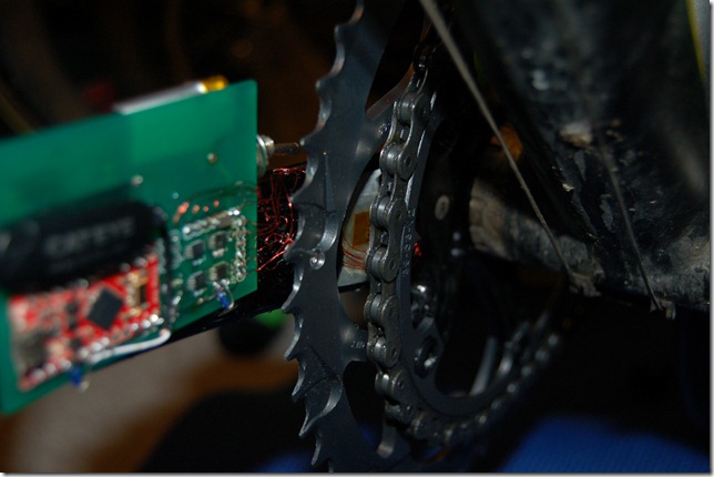
You can see the old shear gauge still inside. It’s a bit of a rats nest of wires down there.


As an aside:

I’ve been sick the last week which has delayed testing and updating. However in my downtime I finally figured out the strain gauge arrangement used by Look Keo Power Pedals! It’s a differential sensor such that it can remove bending moments, that is why it requires 8 strain gauges per pedal. This setup has a decrease in sensitivity but it’s the only way they can make it work. I am thinking about making a video explaining how to do this and why, but it might be a while before I get around to it.

Saturday, February 16, 2013

ADS1247–Now we are cooking with fire!

This little chip is going to revolutionize my design, simplify it, add thermal compensation (if needed, need to do temp testing) and drop the price of the board.
Potentially the electronics might be down to less than 20 dollars ($8 ADC + $2.5 nRF51 + $4 gyro + $6 do-dads) + PCB and assembly. The strain gauges are at 50 dollars + installation, and then an enclosure and battery. Labour would clock in around 8 hours for installation initially, and then overhead.
Some props to TI for the nice part. 451 counts of noise on 24 bit = 2.69E-5, or 0.003%. This is at 10 SPS. I’ll likely be ramping up to 320, 640, or 1000 divided over two channels. This is significantly less than the 32000sps combined (12 – 16k sps depending on calculations). However, to get the noise down to what the ADS1247 is giving me now would requiring averaging techniques.
So effectively I’ve replaced four pricey IC’s, four expensive resistors, and a bunch of board space with a single IC from Texas Instruments. Not bad. Some .netMF code (.NET Micro Framework) for the FEZ Panda II below. Unlike Josh from Josh.to I’m using continuous read. I was hung up most of the day on realizing register 00h resets to 01h and NOT 00h which sets the inputs to AIN0 and AIN0 for both positive and negative inputs, rather than AIN0 and AIN1.
Code after the break.

Friday, February 15, 2013

ANT+ Bicycle Power V3.0

As mentioned in my previous post on the information I found on the new Rotor Power Meter, it became official yesterday that the Bicycle Power Profile is upgraded to V3.0.

What is neat is that it maintains backwards compatibility. What is different is that it adds page 0x13(hex) that defines the metrics for torque efficiency and pedal smoothness. This new page is sent every 1.25 seconds though which is about 1.5 rotations at 90rpm.

Thursday, February 14, 2013

What is going to be in the new ANT+ Device Profile?

I’ve been diligently asking and looking and scouring the web for what metrics the new Rotor Power Meter will contain and now I know. Quote from the www.thisisant.com site:

Balanced measurement
• Individual left & right “power balance” measurement.
• Torque effectiveness (sum of clockwise pedalling power minus anti-clockwise drag).
• Pedal smoothness (maximum torque vs. average torque).

So there we go, nothing hugely revolutionary, and in fact since it’s still a draft standard and nothing. I’m unsure if the new measures of torque effectiveness and pedal smoothness are going to be calculated for each leg (they should) or individually. Ideally it would have options for both options but on a Quarq, SRM, Power2Max could have difficulty showing either because you won’t see anti-clockwise drag, and your max versus average can be skewed and smoothed more easily.

If you measure at 90 degree intervals (just for an example, 16 makes more sense in reality).

Left 0 = 10 N-m, 90 = 40 N-m, 180, = 10 N-m, 270 = –5N-m

Right 0 = 10 N-m, 90 = -5 N-m, 180, = 10 N-m, 270 = 40 N-m

So both look perfectly balanced. Let us say Rotor calculates Torque effectiveness for each leg and has to transmit one value, and therefor averages the "TE” and “PS” Metrics.

TE(Rotor): 10 + 40 + 10 = 60, compared with –5, so lets say a 12:-1 for both, averaging both sides is identical so 12:-5

TE(Quarq, SRM, Power2Max): All have to be summed first, so it becomes

Total: 20, 35, 20, 35 =? 110 : 0

Well that looks different doesn’t it, one is 12:1 and the other is an improper ratio?

PS: Rotor Average per leg = 13.75: 40 = Max, so 2.9:1

Quarq, SRM, Power2Max: Average 27.5 : 35 so 1.27:1

So to summarize, the new metrics appear to only be able to be implemented by L/R meters properly in my opinion. Total meters are going to give way less useful data. Faking L/R by upstroke versus down stroke is one thing and already makes a near 50/50 assumption but the new metrics aren’t so easily faked.
Wednesday, February 13, 2013

More Testing V3 Power Meter and ADS1247

image

Some longer testing (1.5 hours) today and I’ve come to a few conclusions.

  1. My calibration is off
  2. It doesn’t matter that my calibration is off, the crank shear gauge on the inside of the driven arm to measure torque can be skewed by adding a twisting moment to your ankle.
  3. As a result my power balance and power numbers are all wrong! And WAY off from the method of calculating averaged (non-accelerating) power for my Kurt Kinetic Road Trainer.

So I will be adding new strain gauges to V3 on the top and bottom of the crank arm. The arrangement removes bending so it will stabilize and remove this issue. I had said previously that it is the superior arrangement. I didn’t want to have to use two different types of gauges but my hand has been forced. However this raises the question about Stages power meter. What is their arrangement? I suspect it is not a shear arrangement, but rather a double bending arrangement but still on the back side of the crank. It’d lose sensitivity but gains in accuracy.

The ADS1247 is reading out. It’s looking noiser than I want, but this might be a function of my protoboard / power supply / poor wiring / random resistors used as a voltage divider. I still can’t find a potentiometer around my apartment anywhere even though I bought and wired one up specifically for testing months ago. I’ll make a trip to the dollar store tomorrow and hope

Friday, February 8, 2013

Snow Storms, ADS1247, .NETMF, and Friday Night

image

Snow day today which means I didn’t make it into work. Seriously though, I tried. Shovelling out at 8am when the snow was at it’s worse and not a plow in sight. Heard it was going to abate by 10am so figured I’d try again then. Everything I had shovelled looked filled in, waited until 12pm. It stopped, so shovelled again. Test run to Tim Horton’s made me realize it’s a death trap out there. Nothing that my Subaru Impreza with some Falken Eurowinter’s couldn’t handle, in fact I enjoyed it (once I turned OFF traction control). No, the problem is that people in Ontario tend not to buy winter tires, park on the street when they have a perfectly good driveway (filled with snow?), and generally do not know how to drive. In Newfoundland things would have likely remained opened and I would have gotten a coffee downtown with friends in that weather. In Ontario, 200+ accidents, not a plow in sight because they “wait” until it’s over. My street isn’t cleared and more poorly parked cars are now making it improbable to get down the road.

Tuesday, February 5, 2013

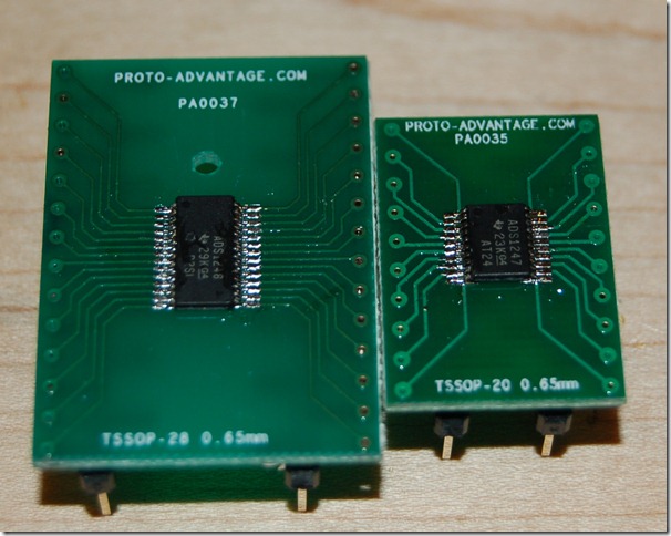
ADS1248 / ADS 1247 Received and Mounted

DSC_9068

I got my breakout boards today for the 24 bit Sigma-Delta ADC’s. Soldered and conductivity tested. Now to wire them to an Arduino and a strain gauge. Approximately 3ma for the ADS1247, 2.048 reference means 5.85ma to each 350 ohm strain gauge setup. Still a little high, but we’ll see. Proto-Advantage was super quick in sending with regular snail mail. I live close to them (Hamilton, ON I think) so it’s not surprising.