Yes, it’s finally getting near the point where I can put this version on a bike and not have to fight with soldering, wires, and tape to hold it together. Anyone who has seen my videos for V2 will remember that.
Sunday, October 28, 2012
Thursday, October 25, 2012
A brief interlude
Currently I have to say that as for interoperable sensors go I think Ant+ is the first time I’ve ever seen anything do better than this xkcd comic about standards. I think the biggest fiasco of it I seen was when NVidia decided to create MXM, a laptop graphics card. They built the standard, opened it to everyone, had ATI (at the time) review it and they gave them back revisions! And then what happened… Well several things happened but suffice to say it didn’t really catch on.
I think that with companies like Look and Polar being very against Ant+ they have made a decision to limit their own market share. At at least that’s how I want to see it, but it’s not the whole truth.
Look wants to go to Bluetooth LE for their KEO power meter, but there is no power meter profile and currently there is already interoperability issues for heart rate monitors using Bluetooth (but I haven’t seen it first hand) that I’ve heard of. Update: DCrainmaker has noted decent interoperability recently with the new LE devices.
Originally I picked up a Garmin FR60 so I could get a heart rate monitor and a ANT+ usb stick cheap. Each device on their own was 50 dollars, but I got the FR60, the stick, the HRM, and the foot pod shipped for 165. For and additional 50 dollars I purchased the bike sensor. This was all to gear up to make my “virtual coach” software which, while poorly written and buggy, I’ve used for the last year. When it became apparent that other people where doing the same and realizing my limited coding ability I decided to revive my strain gauge work and develop this power meter.
This is where things fall apart in terms of standards compatibility. ANT+ is great, but it’s not in phones, tablets, laptops, etc. What is common in these happens to be Bluetooth – we can thank all those hilarious looking people walking around with Bluetooth earpieces and the advent of AD2P for high quality audio in cars.
However, more and more people want to use their phones. I argued against running with my “free” phone, because out of contract it’s a minimum of 600 dollars to replace. That's right, most decent smart phones are 600+ dollars if not on a contract! My laptop didn’t cost that much! However, as I’ve gained faith in my Samsung product I’ve ditched my iPod Nano and now run with the phone. I still think my argument for getting a sensor based watch or GPS watch is valid - durability, price, weight, etc. Even the highest end models are not 600 dollars and are way more robust then a fragile smartphone. Plus my FR60 lasted a year on a single coin cell.
However, whenever I’ve met with anyone about these things the first question is usually revolving around can it be connected to their cell phone. The short answer is “likely not”.
If you have an old iPhone you could buy an adapter, now you have to buy and adapter to plug into another adapter and I haven’t heard for certain if it will work (ANT+ to 30pin, 30pin to lighting). On the Android front it’s worse as the 30 pin apple connector had serial lines, but Android has micro-usb leaving the only option to use some sort of Android IOIO device.
There exists a Bluetooth profile called SPP, or serial port protocol. The AP2 can be hardwired to serial at a specific baud rate. I’m probably going to order one of these and see if I can bridge the AP2 to Bluetooth via serial port protocol. It means that you can have this device on you, or on your bike, or in your bike phone mount.
What’s the downside. Power consumption. This is my nemesis most recently, as it’s an important aspect for the consumer market but many compromises have to be made to achieve it. Bluetooth 2.0 has the SPP profile but LE does not. That means it’s a bit more power hungry. Unfortunately I don’t know how hungry, but it’s worth the 20-30 dollars to get a Bluetooth SPP modem to find out.
Monday, October 22, 2012
V3–Power Consumption
Lets take a look at the breakdown.
| Current (ma) | ||
| Item | 3.3V | 2.5V |
| Bridge | 9.428571 | 7.142857 |
| Instrumentation Amp | 0.55 | 0.55 |
| ADC | 0.792 | 0.6 |
| Sum x2 | 21.54114 | 16.58571 |
| Measured | 35 | - |
| Goal (100 hours) | 2.25 | 2.25 |
I haven’t even looked at the microcontroller current consumption and optimization yet. I’ve been debating my choice of microcontroller, but it’s hard to know what is marketing and what is actually achievable. However I've been debating eliminating the regulator. Rather than using a reference voltage I could go back to my old voltage divider design and then everything is ratio metric. As the battery voltage drops so does the reference voltage. This would simplify things potentially. Switch to the Atmega 328 or the nRF51422 which is my preferred goal.
Update:
Looks like the measured does line up with consumption. I removed the bridge connections and consumption dropped to 15 - 17 ma. This is still quite high, but this is no optimization and running the ADC and Instrumentation Amp at full tilt. So the bridge is pulling similar power as everything else.
Sunday, October 21, 2012
V3–A little too sensitive?
Coming soon, current consumption measurements!
Above is the raw data from the calibration test. I used the setup below with a few weights from my dumbbell that weight approximately 10lbs. Here’s is how it breaks down. As you may realize that the sensors max out at a relatively low load – It’d probably be fine for testing or a 140lbs climber, but not an expected maximum. I have another resistor to set a lower gain, so I might be able to adjust this easily.
What should the maximum per pedal load be. Let’s take a worse case scenario of a 1800 watt sprinter. We’ll assume 172.5mm crank arms and 90rpm.
P = T * w = 1800 = T* (90/60 *2*pi) => T = 191 N-m
T = Lever arm * force => force = T/L = 191/0.1725 = 1107 N = 112kg
Surprisingly my max load with margin is approximately this! However we’d have to account for the downstroke being stronger than the upstroke, so the best way to do this is assume one leg is doing all the work. So in short, I need to reduce my gain to about 125 from 250 approximately. Although I might use different gains as swapping the differential pins for the Right should give me back some sensitivity.
| Left | Right | |
| Zero (bit) | -13273.2 | -5097.73 |
| Loaded (bit) | -17315.5 | -7141.56 |
| Unloaded (bit) | -13286.1 | -5104.38 |
| Difference (bit) | -4042.31 | -2043.82 |
| Load(N) | 44.59091 | 44.59091 |
| Torque (172.5mm) | 7.691932 | 7.691932 |
| Bits/N-m | -525.526 | -265.71 |
| Max Torque (with margin) | 83.80372 | 96.60148 |
| Load (kg) | 49.5228 | 57.08548 |
So I realized a couple of things. Switching the polarity of the supply and ground on the strain gauge also flips the direction it changes when loaded, so I need to swap the signal outputs for the right sensor as it goes negative when positively loaded. The problem is I was hoping to use more of the ADC range by using a lower ref voltage (e.g: –10000 to +32765, instead of 0 to 32765 which allows me to use a higher gain and thus add accuracy). I don’t know why I didn’t realize this in the last post. I’ll look at this fix tomorrow or Tuesday.
I’ve left it running for approximately an hour and it’s holding steady at –13273 +/-4 and –5097 +/3.
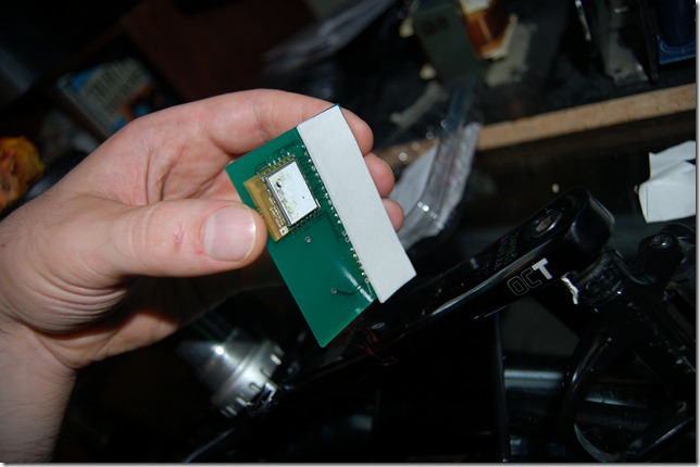
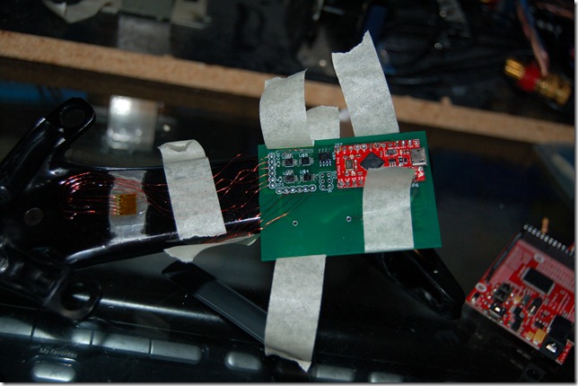
A little two sided tape holds the board on nicely two the back of the crank arm. Should nicely clear the crank ring too!
Tuesday, October 16, 2012
V3–Reading Sensors, Transmitting Power Data
If you are good at reading between the lines you’ll understand that the title alludes to two separate tasks, but they have not been combined.
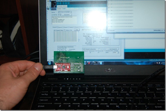
So the short is, the AP2 module, after a lot of fighting, is talking to the microcontroller. I was concerned when I couldn’t get the AP2 Module surface mount soldered (with only a soldering iron). It was very discouraging but I eventually solved it. This was already mentioned, and a dummy program was loaded up to transmit meaningless data on the basic power profile. See below.
So the next thing was soldering on all the MSOP and SOIC components which turned out to be very easy by comparison. I guess I’m getting good at soldering tiny components by hand. So I loaded up my dummy program that reads the raw sensor data from the ADS8321 16 Bit ADC. It works fine and at a gain of 250 (using 2.5 dollar 0805 resistors instead of 15 dollar through hole resistors) gives great sensitivity.
This is going to be a bit technical but bare with me; the ADS8321 is a differential ADC so it gives –32768 to +32765. My instrumentation amp, the AD623, is a single supply differential instrumentation amp, so a reference voltage is used to raise the voltage. So we could have +/- 4mv differential, for example, but once amplified it could be +/- 1v. Since we have a single supply this needs to be raised as we can only go from 0 to +vcc. Imagine we have a 2v supply voltage, we would want to lift the 0mv differential after amplification to 1v so that we have a full range for the +/- 4mv swing corresponding to +/- 1v after the amp. This gives a range of –1v corresponding to –32768 and +1v to 32765 all from the original input of +/-4mv.
I’m using a 3.3V regulator to provide the supply voltage, but I only really care about one direction of the force so what I was expecting was the voltage to always go in one direction. HOWEVER, a strain gauge has a tolerance so you might have an offset electrically. This is more of a problem because if you don’t use a reference voltage to raise the level sufficient and it’s hanging out at –1mv and you are only reading positive voltages, you have a dead sensor area and then a massive offset when it kicks in. So it still needs to be raised, but not necessarily by the whole range. In my case I’m raising it 1.024v with the LM4140 precision reference voltages.
If you are still there this all culminates in one of my bridges has the supply and ground swapped as it’s going in the reduced range direction when I apply a force that wouldn’t freewheel the bike.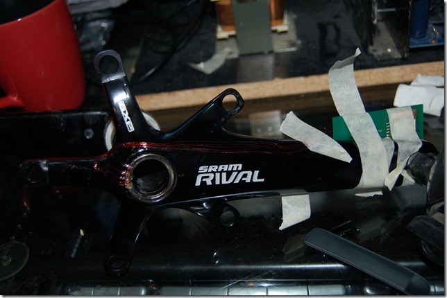
The next steps are mounting the PCB more securely and switching to coin cells. I currently have concerns regarding coin cells as my drain might be too high in which case I would switch to my Li-ion cells I have already. Power Management will be a very important part of development from here on out. Power reduction hasn’t been at the top of the list and I still wish to change to the nRF51422 Soc when the evaluation kits become available.
Once I can get a handle on the current consumption I’ll post the results.
Friday, October 5, 2012
V3 Progress
I've received all the components to complete the V3 circuit board. Surface mount soldering by hand is generally difficult, but the AP2 modules are proving to be the absolute most stubborn pieces to solder that I've had the displeasure of attempting. This is a situation where you need to accept the old adage: "The right tool for the job". I am not using the right tool.
If you attempt to surface mount the AP2 module by hand here is something to keep in mind. There are small through holes for the contacts on the base, just big enough for a fine leg of a resistor to fit down. They also make great test points. If you test and cannot get the solder on your PCB to connect to the AP2 then put a wire down the hole tinned lightly with solder. Heat the wire and keep pushing it down, then alternate heating the pad on your board (the small amount exposed) and the wire while applying pressure downward. Eventually you'll make a connection. Check it with a multimeter. Once you've made a good connection heat the pad and then the wire and put the wire out -- it will pull solder up through the hole and seems to make a very reliable connection.
This is time consuming. I spent about 3 hours trying to surface mount two of these to my PCB and several connections would not connect. This technique takes several minutes per contact, so about an hour to get all the connections working. All of this could have been avoided if I had a reflow oven. Necessity is the mother of invention.
Monday, October 1, 2012
V3 New Circuit Boards
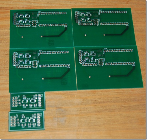
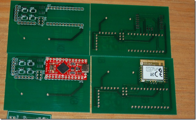
As you can see above the new circuit boards have arrived from Alberta Printed Circuit Boards. These guys have some of the quickest turn around I’ve seen – you do pay for it though. I’ve designed this board to not deviate too much from the smaller circuit boards I initially built – mainly to speed development of the V3.
A previous post showed a circuit board with an atmega32u4 chip and the associated circuits to support it. Considering I do not have a reflow over I opted for the simpler approach of only supporting the analog and wireless on this PCB and leaving the regulator and micro-controller on an Arduino pro micro. You can see how I broke out the ISP to make it more convenient to program.
Both of the boards mount to this main one – one via pins and the other via surface mount. I haven’t, but I should, incorporate power planes but I consciously did not include them as the AP2 module suggests not having anything metal under the F-Antenna. I probably took this to the extreme but after the difficulties with V2 maintaining a good signal I felt this was a good choice. The analog components are very very low power, on the order of micro-amps of current draw at 3.3v and I never had issues with the little circuit boards so I’m comfortable.
The voltage divider used on V2 is replaced with a precision voltage reference, the LM4140.
This will go on a bike without too much problem but having seen the size of the “Stages” power meter I’m keen to drive the size down. This would have been a great time to know some electronic engineer who works at any of the mobile phone companies as they can pack some power into a small space.
I’m keen to use the AP2 module as the nRF51422 hasn’t become available yet. I unfortunately missed my opportunity to get a free one as I had to renew my passport (Expired on the 25th of Sept, and the Boston conference was on the 24th). So I couldn’t book tickets or sign up for the tour, and as a result I’m waiting for nuhorizons to get in the evaluation kit.
I just submitted my order for parts with Digikey just then, so maybe a new prototype by the end of the week, but likely next week some time.


