Wednesday, September 19, 2012

V3 Development–Board Design

The most challenging part to the design and development of a power meter is certainly the packaging – or maybe it’s the programming, either way it’s actually not the instrumentation side of things. I think I’ve found a way to package the electronics out of the way and not interfere with the RF signal which was an issue with V2. I’m planning to move to the nRF51422 eventually but until then I’m using a hobbyist microcontroller board to speed development. The new board is to be mounted to the inside of the the chain ring side crank arm. The AP2 module will hang off behind the arm. This means there is no metal near the module to interfere with the signal. I still need to incorporate the battery. I might take the Rotor route and use the higher capacity cell rather than the 2032. Perhaps the 2477 cell.

The unrouted trace is a ground, there are multiple grounds and I’m avoiding ground loops.

image

Tuesday, September 11, 2012

V2 Working Video


This video is just meant to show my V2 prototype working. There is several bugs in the firmware so far, rotatably it doesn't reset the accumulated torque reading if it hasn't made a revolution in a while. This leads to the period timer overflowing, causing a miscalculation on the first revolution, but subsequent revolutions are calculated correctly.

It needs work -- that's why I'm building V3. The hope is that I'll have compact reliable electronics that I can continue to develop the firmware for. If you're keen you'll notice a lot of failed Rx on the laptop. Antenna placement is critical and placing it inside that torque tube is a terrible idea.

Sunday, September 9, 2012

V2 Torque Testing


Unfortunately I've been sick since Friday and I wanted to get more done this weekend than I did. This evening I felt good enough to record some short testing of the V3 and show a little of V2. Enjoy.


Friday, September 7, 2012

V3 Power Meter–Initial Instrumentation

DSC_8933
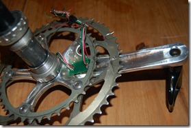
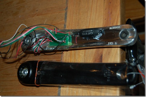
Earlier this week my new crank arrived ready to instrument. The above picture is the new crank with V2 Power Meter (currently disassembled). The new OCT hollow cranks have a flat back instead of the grooved out backing of the old pre-OCT model. This is exactly what I was expecting for two reasons.
DSC_8934DSC_8935
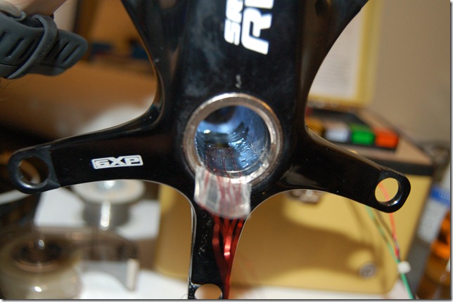
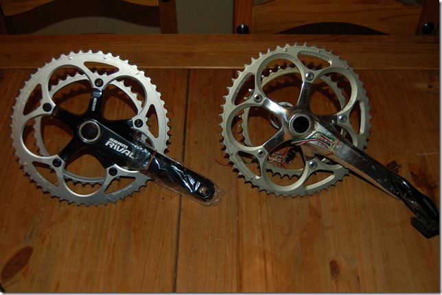
The first reason being is that the flat back is easy to mount to. Secondly, and more importantly, if a shear gauge is used to measure the drive side arm it can be placed on the inside and is thus protected. Another view is of the non-drive side arm shown below.  In V3 the non-drive side arm will not be instrumented. The torque tube that goes through the bottom bracket is instrumented instead. No wires to be run through the crank, or like Vector or Rotor, both sides do no require batteries, a master and a slave connection and the associated issues.
DSC_8938
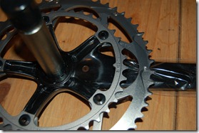
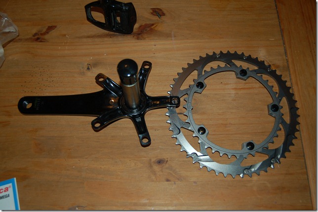
The first thing is to remove the chain rings as they get in the way. I didn’t do this on the previous builds. The loctite on the chain rings tend to make them very difficult to start backing off. I was getting some very large flex in my Allen keys. Two socket drivers work best, or a socket driver on the small side and an Allen key on the other.
DSC_8936
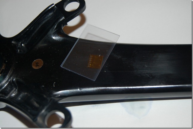
On that singular polymide backing is 4 strain grids. There has been some confusion caused by power meter manufacturers. A gauge is the grid(s) on a polymide backing. In this cause this is one strain gauge that has four sensing grids. However for marketing purposes this would be referred to as four strain gauges. I could use single grid gauges but that is an inherently flawed design that is more time consuming. It’s primary flaw is that each grid could be aligned poorly, there is a greater propensity for a bad glueline, harder to mask the areas, etc.
DSC_8939
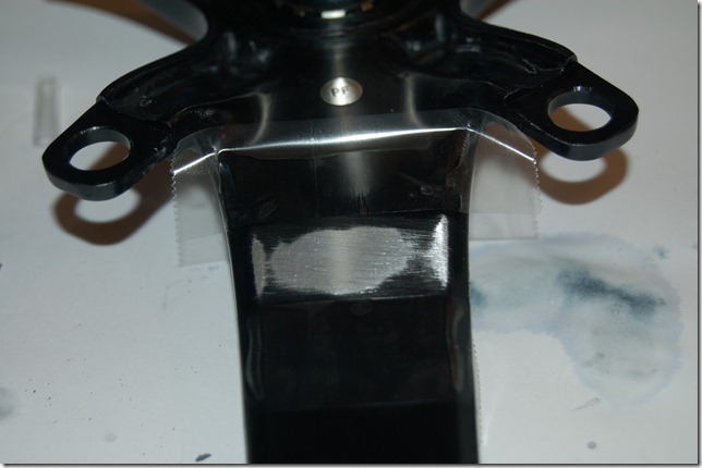
I used masking tape to mask off the area but when using Vishay Conditioner and sanding with 180, then 320, then 600 grit paper destroyed it very quickly. I masked the area with PCT-2M tape instead and continued sanding. This or their MGJ mylar tape works best for masking.
DSC_8942
After sanding with conditioner, flood the area, wipe with gauze, then flood with neutralizer and scrub with cotton applicators (Q-tip with wooden stick) until no more metal residue comes up. Flood with neutralizer again and then wipe away with clean gauze – do not reuse, wipe in one direction only, and don’t wipe with anything that contacted your sink. Those oils can ruin the glueline.
After cleaning a piece of glass or plastic with neutralizer, place the gauge down and use the PCT-2M tape as shown to pick it up. Remove the tape and gauge with by peeling back at a shallow angle.
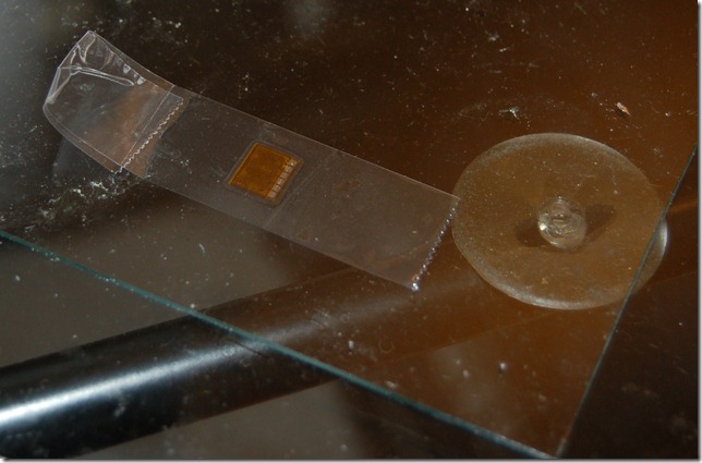
DSC_8944
Apply to the prescribed area. Peel the tape back, again, at a shallow angle, apply accelerator, wait for it to dry, then apply glue to the surface just before the gauge and wipe the gauge down with gauze from back to front, then apply finger pressure. The APP Note from Vishay best describes this and it requires some practice to get right.
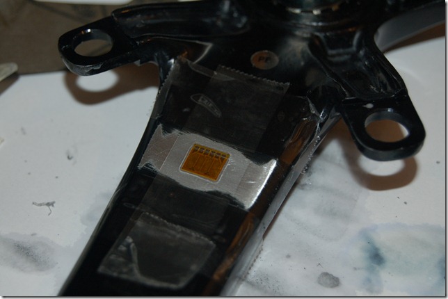
DSC_8945
While waiting for this to dry onto the hard part. The gauge in the hole. The gauge needs to be laid on a clean metal surface because the wires will need to be soldered to it. Cover the gauge except the contacts with PCT-2M tape.
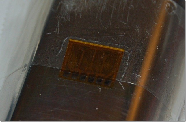
DSC_8949
Now, painstakingly apply flux, tin the contacts, tin the fine magnet wire, and solder on the wires. It’ll start looking like the picture below after using solvent to remove the tape ever so carefully.
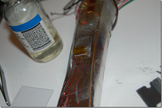
DSC_8950
Place the gauge in a clean bottle of solvent to remove any flux or residue.
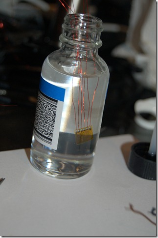
DSC_8951
The next steps were impossible to really photograph, but I did manage to get me applying pressure to the gauge while it’s in the hole.
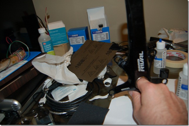
DSC_8954
It’s hard to see but the gauge is in there.
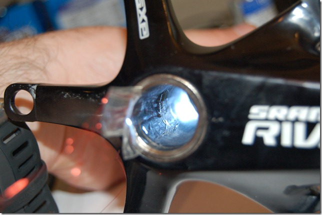
DSC_8961
Using the M-Coat A, the inside gauge is coated and let to set.
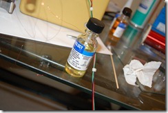
DSC_8965DSC_8964
Below is how the soldering looks on the arm. This is then flooded with solvent, let dry, and then coated with M-Coat A. The gauges have their resistance checked by a Vishay Gauge Installation tester 1300. These pricey little old school looking boxes are high quality resistance measurement units. They can also measure in the Gohm range for resistance to ground and do this with 10VDC which is safe for almost all gauges.
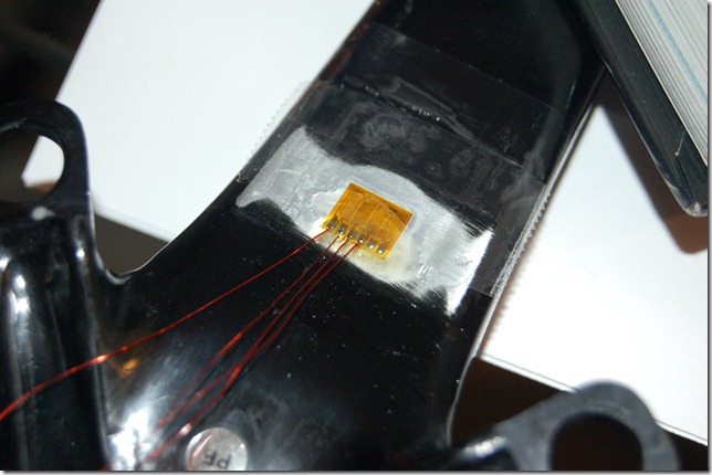
DSC_8974
More updates coming soon. I have a National Instruments Compact DAQ this weekend that I will be testing the installation sensitivity with.

V3 preview

I've been busy with applying strain gauges to the new Sram Rival OCT crank.  These are the omega double shear gauges that were posted about earlier.  Some interesting photos but I did not take video.  I've found that when it comes to precision work this feels like someone watching over my shoulder.  Maybe in the future but for now I'll just be describing the application process.  One of the gauges presents a real challenge for application.  I'll be posting more details and pictures tomorrow.

Sunday, September 2, 2012

EuroBike, Quarq, Pioneer, Kurt Kinetic

Text post today as I'm still waiting on parts to arrive. I'm anxiously awaiting availability of the nRF51422 Dev Kit and debating going to the Global Tech tour in Boston, MA on the 24th of Sept.

I knew it wouldn't be long before I'd see Rotor's new slightly reduced size version of their power crank. Essentially the exact same idea I had and apparently it is licensed from the old MEP powermeter which decided to use Bluetooth instead of ANT+. What I didn't know is that they were on track with a pedal stroke analysis algorithm which is something I've been working on using error measurement analysis theory I developed in my Engineering Masters degree. Apparently they are also working as an ANT+ Alliance member to update the power profile to include this. That's good as it'll be a direct implementation to V3 once  I get the basic and crank profile code cleaned up. Though I often wonder why we haven't seen an influx of Chinese companies since most designs are based on an expired patent and therefore not patentable.

It does look like Rotor is taking a dig at the Quarq and SRM decoupling Algorithm here by saying:

"Independent positive and negative power output. unsurpassed accuracy due to symmetrical crank deformation with 8 strain gauges (no need for extensive calculus or data ltering)."

What does this mean. Well, it's just saying they (and by extension, my design) doesn't require a more complicated decoupling algorithm. I suspect they mean "altering" and not "ltering".

Pioneer has released a new attempt at a power meter which I have huge reservations about. This is not about the "how" it's just about the glue -- literally the glue. Strain gauging can be done in a few ways. "Lick-and-Stick" which means Cyanacrylate glue, a high quality crazy/superglue, or higher temp cured epoxy. Well the second won't be happening as a LBS will need to bake the bike crank for up to eight hours. Improbable. There are almost room temperature cured epoxies that require specific clamping pressure but generally not recommended for transducer quality installations. Essentially you are trying to get a LBS to do a precision technician job. I think that this could lead to people with poor reading power meters if this gets to market.

Looks like someone was working on the same thing as I did but put in more than the two evenings of two to three hours of work. What I'm referring to is this and my own Arduino style version here. It's Bluetooth smart, which I have no idea about. I suspect it's the sports implementation of Bluetooth LE. It uses a similar algorithm as I previously indicated of

Power = regressed curve + Flywheel mass moment of inertia * angular acceleration * mean angular velocity over sample period

and in a coast down this becomes

regressed curve/angular velocity =  Flywheel mass moment of inertia * angular acceleration

More updates to follow. If I can get the bike crank this coming week I'll do some documentation on how to install strain gauges.